

These are things I hear over and over again talking to CNC’ers. There are some better ways and some better answers that can really improve your feeds and speeds practices, if you’re open to them. Fixing your feeds and speeds is one of the easiest productivity hacks you’ll ever make.

Don’t get sucker punched assuming Feeds and Speeds cure all problems! I often hear from folks who are breaking tools, but assuming they use our G-Wizard software (ok, or something just as good!), the problem is seldom feeds and speeds. They have assumed that since their end mills are snapping right and left, it must be a feeds and speeds problem, but the truth is,they are just one part of the much larger puzzle, albeit an important part. Here are some of the more common problems I’ve come across that are not feeds and speeds issues:
- Failure to use some form of lubricant when cutting aluminum. This is probably the number one error, and with the advent of inexpensive router-style CNC machines, it has become extremely common. Folks, aluminum has an affinity for the cutting edge of your end mills. It literally wants to bond or weld itself to that edge.Once it does, tool breakage is inevitable. The best way to prevent this is to use some form of lubricant–flood coolant or mist being the best choices. Even spritzing the cutter every now and then with a can of WD-40 will work. If you can’t lubricate, you need to find a way to clear chips immediately from the cut and avoid much depth of cut at all. Even then, chip welding is a ticking time bomb.
- The second most common error I run into is excessive run-out. Heck, it’s even happened to me – I broke five 1/8″ endmills in quick succession as I trial-and-errored my way to finding that I had a bad ER32 collet. DOH!Runout is additive to chip-load, and too much chip-load is what suddenly breaks end mills. Runout is always present, it’s just a question of degree. It is in your spindle, tool holder, and collets. You can get a handle on it by measuring it easily. Dealing with it ranges from easy (replace that bad collet) to difficult (get a spindle or machine with less runout). The smaller the cutter, the less tolerance for runout it will have.
- Using too many flutes in a material like aluminum. Aluminum requires fewer flutes because it produces bigger chips that curl in a way that takes up a lot of space. It needs more space between the flutes of your end mill, and end mills with fewer flutes have more space. Stick to two- and three-flute end mills, unless you really know the sneaky ways to cheat on that rule.
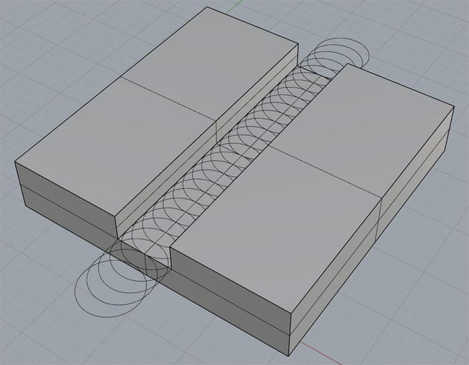
When we want to be safe, we instinctively slow down the machine. But, it turns out that can actually be the least safe thing you can do in terms of tool life. A slower feed-rate for a given rpm results in a lower chip-load. That’s fine, to a point, but you can get to a point where the chip-load is so low that the cutter can’t efficiently make a chip. Instead, it starts to rub or burnish the material rather than slicing off chips cleanly. We can see geometrically how this happens with the following diagram:
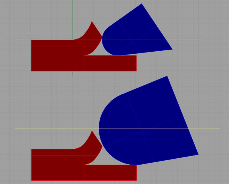
Cutter at top can slice off chips, cutter at bottom is “rubbing” them off. Imagine the cutting edge is actually rounded rather than ending in a sharp point–they are if you look at them under magnification. If the top of the material lines up above the centerline of the cutting edge, all is well, the edge can get under the material to slice off a chip. But if it is below that centerline, then the cutter is spending more time pressing down than slicing up. It plows along the surface trying to rub a chip off. This produces tremendous heat which will in turn dull the cutter and make the problem worse. How can you tell what the minimum speed is you should allow? It’s not easy, but we’ve done the research here and our G-Wizard Calculator will give you a rubbing warning. Absent a tool like that, a rule of thumb is don’t get below 1/4 of the recommended chipload for the tool. Let’s take the alternative. We’re charging along in the cut and all of a sudden there’s a noise. Suppose we reduce the spindle rpm without reducing the feedrate? Very bad idea–reducing rpm at the same feed-rate kicks up the chip-load and will likely break your cutter. Always reduce feed-rate first! Here’s one more example. We enter the cut, perhaps it’s a nasty parting off cut, and suddenly there’s loud chatter. Again, our instinct is to slow down. But chatter is a resonant phenomenon. It’s just as likely to stop if you speed up as slow down–so be sure to give both a try. Chatter is actually very manageable if you understand a little bit about how it operates. The chapter on Chatter from our Free Feeds and Speeds Tutorial will give you the tools you need to tame Chatter very quickly.
Ignoring Cut Depth and Cut Width in Favor of Feeds and Speeds
Did you know that an awful lot of what’s going to happen to your cutter is decided by the cut width and cut depth you choose? Taken together, the two are huge determiners of how well chips can be cleared, especially in drilling holes. Our ability (or inability for deep cuts) to clear chips determines how much we have to penalize the cut from the optimum chip-load values we might otherwise entertain. HSM toolpaths are highly sensitive to optimizing cut depth and cut width. So we should minimize both, right? Not so fast! There are pros and cons on both sides–let’s look at the pros of increasing cut depth or cut width. Deeper cut depth makes chip clearance harder, but it spreads wear over more of the flute length which can be critical for tool life. It reduces wasted motion as we step down over and over to reach the full depth of a pocket. Similarly, if we use too little Cut Width, we encounter a phenomenon called “Radial Chip Thinning.” It makes us move the cutter faster than expected to achieve a target chip-load because the geometry of small cut widths results in smaller chips in an odd way. There’s a lot more at work than the factors I’ve mentioned. When you choose a cut depth and cut width you’re locking down a number of trade offs and constraints on the feeds and speeds that you’re probably unaware of. The game is all but won or lost by the right choice, yet most CNC’ers are not choosing their cut depth and cut width in any particularly scientific way. They may use very fancy tools to choose feeds and speeds, but if the cut depth and cut width aren’t similarly optimized, you’re wasting your time–you simply get can’t the best results. Simple rules of thumb can’t capture such nuance, but our G-Wizard software has 2 different tools that make it easy to choose good values for Cut Depth and Cut Width so the rest of your Feeds and Speeds calculations will be singing in 3 part harmony. My favorite is CADCAM Wizards because it is so quick and easy. It asks very few questions and returns a complete Roughing and Finishing Feeds and Speeds Recipe for all common CAM operations (hence the name CADCAM Wizards). Here’s a video that shows how they work:
CADCAM Wizards work their magic by testing hundreds of combinations against the G-Wizard Cutting Physics Engine to determine the best set of trade offs for the holistic cut recipe. That’s not something you can do in a spreadsheet or with your yellow pad and scientific calculator, particularly not as quickly and easily as CADCAM Wizards does the job.
Treating Feeds and Speeds as Tables
Speaking of CAM, yellow pads, spreadsheets, and scientific calculators, I run across so many CAM programs and CNC’ers who want to view Feeds and Speeds as tables. I guess they’re so used to seeing tables in tooling catalogs that it seems like the right way to think about Feeds and Speeds, but it is absolutely one of the worst ways to think about it. Here’s the thing–the physics of Feeds and Speeds are much more complicated than any simple set of tables can express. But tooling manufacturers have to tell you something, and at least until recently, they felt they had to tell you something in a paper tooling catalog. So they over simplified it, boiled it down to tables, and hoped for the best. The problem is the tables can’t accurately reflect the whole story. You can see clear as day that they know they’re not telling the whole story when they provide a range of answers. I’m looking at a catalog right now that says the Surface Speed (SFM) range for Aluminum with their endmills should be 500 – 1000 SFM. Nowhere does it say how I’m supposed to decide which one it is, yet that’s a 2x range. They can’t be more precise than that because tables can’t account for enough variables to be very precise. We see something similar with chiploads. If you think about it, each table is 2 dimensional and therefore handles 2 variables. G-Wizard considers over 50 variables as it’s making Feeds and Speeds Calculations. Every single one of them impacts the outcome. How many variables are you considering? The average table is good for 2 variables. If you’re cranking the data through a sophisticated Excel spreadsheet, you might pick up a few more. But what’s the effect of the ones you’re still missing? Based on the feedback of our customers, the impact can be extremely large. They started out using these simpler methods and report large increases in their results with G-Wizard:

These are the kinds of results our customers tell us they get from G-Wizard…
Ignoring Tool Deflection
Tool Deflection: Silent Killer of Tools and Productivity? It may be surprising to learn, but tool deflection may be the biggest silent killer of tools out there. Most CNC’ers are not even aware how much Tool Deflection they’re dealing with on a particular cut–you have to use a Feeds and Speeds Calculator that tells you this figure before you’re really aware of it. Once you do know it, you’re probably not real sure what it means or how much is too much. Rather than dive into all that right here and now, let me give you a couple of pointers. First, a good Feeds and Speeds Calculator like our G-Wizard will tell you exactly how much deflection you’re getting and it will warn you when there is too much. Second, it will give you tools to deal with the problem of Deflection. G-Wizard has a Rigidity Calculator that can help you determine the effect on rigidity of tool diameter, stickout, and material (Carbide vs HSS). It has a Cut Optimizer that will tell you how much Cut Depth you can have for any given Cut Width and vice versa. And it has CADCAM Wizards, which will automatically run through hundreds of combinations to find the optimal pairing of Cut Width and Cut Depth for best efficiency. Here are some good pointers to help you learn more about these tools:
- 11 Feeds and Speeds Considerations for Lightweight CNC Routers: Has an awesome discussion of the Rigidity Calculator and uses it to show how to choose sturdier cutters for your job.
- Tool Deflection Sourcebook: Everything you ever wanted to know about Tool Deflection and more in this in-depth article.
- 2 Tools for Calculating Cut Depth and Cut Width: Nice easy walk-through of how to use Cut Optimizer and CADCAM Wizards.
Check these articles out, and remember, you can’t get tools like these anywhere else but CNCCookbook’s G-Wizard Calculator.
Not Taking Advantage of all the Great Tips Out There

In school, they teach feeds and speeds as a set of simple formulas–here’s how to calculate rpm from surface speed and tool diameter. Here’s how you calculate chip-load. If you’re lucky, they get past those few basic formulas we can find anywhere (like Wikipedia) and on into the next level of detail. That next level of detail boils down to adjustments that have to be made to the formulas so they reflect reality, rather than the ideal that is theory. For example, if the Cut Width is less than half the tool diameter, you must adjust the feedate to account for radial chip thinning. That next level of minutia adds a couple of dozen additional formulas you must apply and a bunch of new variables. For graduate level work, perhaps they’ll get into the next level of complexity which will involve optimizing some of these variables relative to one another, something G-Wizard does extremely well that is unique in the Feeds and Speeds world. But there is yet one more level of knowledge to be had. Once we understand how all those different variables and formulas interact, we come to realize that the world of Feeds and Speeds is far from uniform. It’s a tangled landscape with many interesting cul de sacs, side streets, and neighborhoods. We talked about the rubbing phenomenon above. That’s one interesting neighborhood, the one you reach if you allow chip-load to fall too low relative to the tool’s sharpness. There are many more. Here are some examples:
- Above a certain threshold of Cut Width, it is advantageous to switch from Climb Milling to Conventional Milling. It turns out that while most CNC’ers always Climb Mill, they’re missing out on cases where Conventional Milling actually results in superior geometry. The reasons are vaguely similar to those that cause Chip Thinning.
- Drilling Deep Holes, where depth is measured in tool diameters, can be something of a Black Art. There are a variety of little neighborhoods where one technique works better than another–peck drilling, parabolic flutes, how far to retract, how often to retract, and so on, all play a role.
- You can substantially change the rules if you can introduce High Pressure Coolant, and especially Through Spindle Coolant.
- Even just precisely aiming the Coolant using a Programmable Coolant Nozzle can afford you advantage.
- How your spindle’s power curve matches up to the rpm and surface speed trade offs of your tool and material combination matter. The point of maximum material removal may not be the ideal point for the tool. Instead, it might be shifted towards the place where your spindle makes maximum power.
- There are peculiar combinations of soft material and spindle limitations where HSS can actually remove more material than carbide.
I can go on like this for some time. There are literally hundreds of these little nuggets out there, waiting to be discovered. You see them in tooling catalogs which mention dozens of them. Others you have to discover for yourself by experimenting with combinations. Some are so subtle, you’d never find them unless you have help from software that’s trying devilishly hard to maximize the combinations. When I first started the journey that resulted in G-Wizard, one of my biggest challenges was trying to figure out how I would remember all of these helpful little rules. There were so many of them, and every time I opened a Tooling Catalog, more would spill out. I finally gave up and decided I wanted software to remember these things for me. It should tell me the best hints and tips once it saw which neighborhood I was in by virtue of the parameters I entered. That’s how G-Wizard’s Tips feature was born. Take advantage of all those nuggets. Leaf through the technical sections of your Tooling Catalogs–that’s what they are there for. Or get a Digital Assistant like G-Wizard that will remember them for you and remind when they’re applicable. I’ve gone through some 250 tooling catalogs now, combing them for such tips to add to G-Wizard. I still get excited to go through the next one I get my hands on too!
Choosing “Good Enough” Feeds and Speeds
A lot of folks figure what they’re doing for Feeds and Speeds is good enough. After all, you’re not breaking too many tools, you’re making money on machining jobs, and the cut sounds good, isn’t that enough? Typically only the Beginners step up with a desire to solve the problem well because they don’t already have a solution they perceive is working. But the Beginners will have their only flavor of Good Enough that comes in the form of insistence on free tools. But here’s the thing–it’s really not hard to do better and the benefits of doing better can be quite large for almost any CNC’er. We’ve traveled through some of the less traveled Feeds and Speeds roads in the discussion above. I hope you can see there’s probably a lot you’re not considering if you don’t use a sophisticated Feeds and Speeds Calculator. Spreadsheets and Tables don’t do enough. They can seriously reduce tool breakage, but that leaves a lot of room for further valuable improvements. If you’re getting half the tool life that’s possible (and that our customers tell us was the typical improvement they got), you probably don’t notice it. Tools go for quite a while before breaking, BUT THEY COULD GO A LOT FURTHER STILL! If your surface finish is decent, you probably don’t think about it. Yet, if you could improve it, you might save a lot of time by reducing the amount of work that happens after the part comes off the machine. Then there is your time spent, whether on a job that takes longer than it should, or time spent wrestling with handbooks, tooling catalogs, calculators and spreadsheets. Time that could be put to better use. I have folks tell me they don’t need anything better because they can hear good feeds and speeds. You can hear really really bad feeds and speeds, but you can’t hear good feeds and speeds. The range of combinations your ear will tell you is a good one is much larger than the optimal combinations. If you could hear good feeds and speeds, you could by ear training CD’s and companies like Boeing would make all their machinists listen to them. You’d have to take an ear test to get a good job. Hobbyists frequently tell me they can’t afford a tool like G-Wizard. They’ve purchased or built a machine for at least $1000 and probably a lot more. They’re buying cutters for that machine and the average price of a cutter is a significant fraction of a 1 year subscription to G-Wizard (good for a 1 HP spindle for life!). If they save even one cutter during the course of that year from an untimely demise, they’ve mostly paid for it. And they’re certainly the ones most likely to be breaking cutters and most in need of help. Did you learn everything you needed to know and broke only 1 cutter in the process? They feel time is free and not something they should try to save. Yet, they have many projects they’d like to get made and not enough time to do them all. For Pros and Hobbyists alike, improving your Feeds and Speeds is one of the cheapest and easiest productivity hacks you can make.