This article is in reference to a previous article and class from Autodesk University related to surface finish.
Today we’ll look at the steps used to mill a scaled-down version of the Autodesk Fusion 360 reciprocating saw demonstration and training part. This is just one of several methods you can use, and you may have your own preferences. Feel free to share your tricks and experiences in the Comments section!
Inspiration
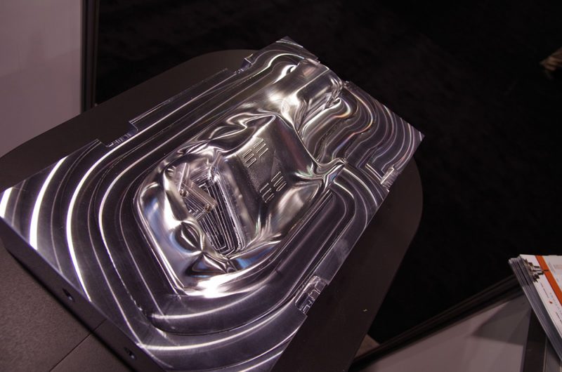
The inspiration is the same part, milled full scale, by Titans of CNC and is used as a display piece by Autodesk at tradeshows. Titan's piece is fantastic, with a really good finish, but it also weighs about 60 pounds and is fairly difficult and expensive to ship to all the shows. (See Titan's YouTube video here.)
Our goal: Mill a smaller version to use as a simpler, smaller showpiece. We wanted to mill it on a PCNC 440, scaling it down by half to fit into the work envelope.
The question: Could we get a surface finish comparable to the VF6 SS from Haas that Titan used?
For reference, here’s Titan's part:
Roughing
For the roughing, we used a 3-flute streaker from IMCO: first a 1/2-inch diameter cutter (0.52 DOC, 0.05 WOC) to remove the bulk of the material, then a 1/4-inch diameter (0.26 DOC, 0.04 WOC) for re-roughing or rest material roughing the leftover stock. You can see the operations in this slideshow:
When the 1/2-inch tool was finished, we had a part like this:
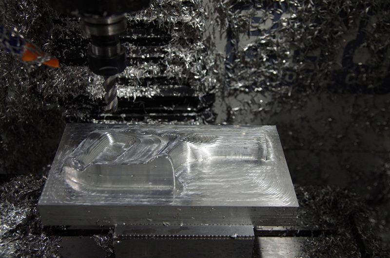
There was extra material left over inside the pocket for the grip/handle, which needed to be removed by a smaller tool. Also, the stair steps were fairly large for the semi-finishing tools, so we wanted to reduce those, too.
You can automatically re-rough the leftover material — that’s what the rest material option is for. Rest material can be the whole setup tock, an imported model, or (the method we used) the material left over from previous operations.
If you use a second adaptive clearing operation, you may get some undesired air movements depending on your parameters and tolerances. John Saunders from NYC CNC did a really good video on removing the whisper cuts (see here), but those tactics don’t always work on 3D-contoured parts, plus we actually wanted additional cuts to reduce the original stair steps.
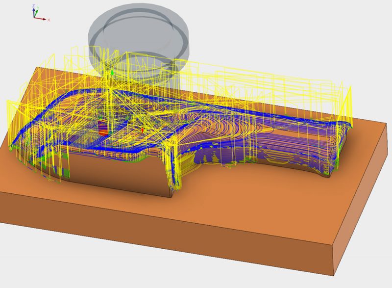
Alternately, you can run the adaptive clearing just inside the pocket so that the full material is cleared away, then run some other cutter path everywhere else. In this case, it’s a contour cut.
Together, the two cutter paths allow for a smoothing of the rough model.
Here’s the roughed-out part after the 1/2-inch and 1/2-inch roughing:
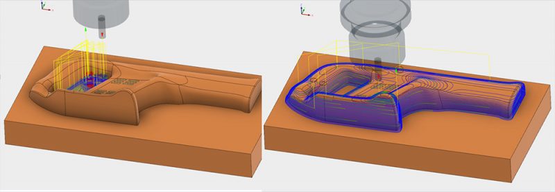
Semi-Finish and Finish
Although there are many different finishing strategies you can use, we chose a combination of a parallel cutter path (planar finishing) and the contour cutter path (Z-level finishing) using a slope option. (For more information on the differences in strategies, and the benefits of this one, see here.)
We used this strategy for the finish and semi-finish; only the stock allowance and stepovers differed. With semi-finishing we left 0.005 inch of material for a finish cut with a 0.020-inch stepover or stepdown. With finishing, we cut to net zero, with a 0.005-inch stepover. The two cutter paths worked together to completely cover the part, without large cusps or scallops remaining.
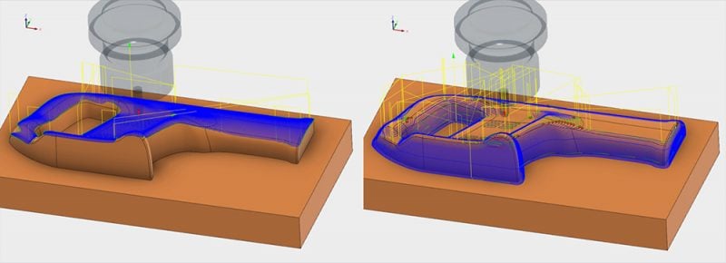
Here’s what the part looked like after the semi-finish operation:
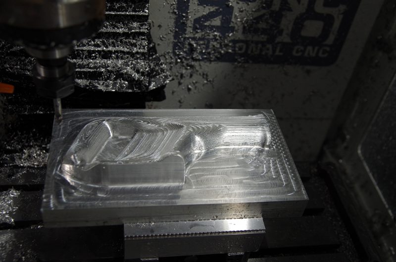
And during the actual finish process with the 3/8-inch ball:
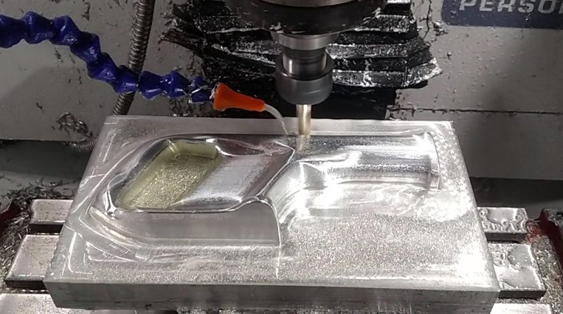
We used a 3/8-inch ball mill for most of the finishing, as it deflects less than a 1/4-inch one and still mills all of the part’s radii. For the very bottom of the part, we used a 3/8-inch bull nose with a 0.015-inch corner radius to get a relatively sharp corner, yet still achieve a smooth finish.
You can see the operations in this video (sped up for time):
Tips
During roughing operations, we had to pause four times to remove chips from the enclosure. Even so, many of the images during roughing show a lot of chips in the mill.
With ER20 collets, it’s easy to have excessive runout if they’re tightened too much or incorrectly assembled. So when finishing, it’s important to check the runout in the tool and tool holder before milling. We checked and adjusted until we minimized runout, though we were never able to get it to zero.
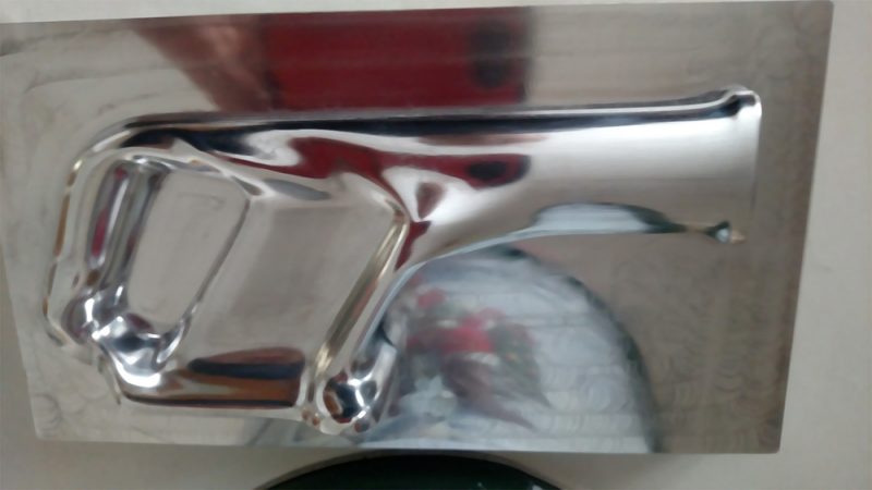
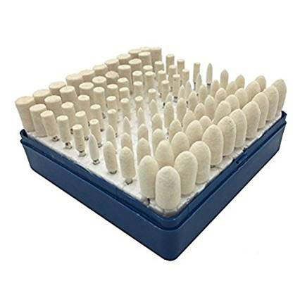
Polish
While the part isn’t hand-polished, it is polished, allowing us to share another tip on surface finish:
I have a friend that made small molds for the badges placed on cars. He would set up several on his mill at one time, program all the parts, hit cycle start, and practice some golf. Afterwards, he would place a small polishing bit in with some compound, make a 3-axis CAM program for that, then let the machine run while practicing more golf.
In this case, you can use Dremel polishing bits with a 1/8-inch shaft. Simply place some polishing compound on your part and use the polishing bit in your mill with a 3D cutter path like scallop. Let it go while you practice a round of golf, or do other work around the shop. For this part, we used the large cylindrical bit, about 0.42 inch in diameter, and a spindle speed of 9000 RPM.
Milling 3D-contoured parts is quite different from milling prismatic parts. With careful programming and strategies, excellent surface finishes are possible, even with small, inexpensive mills.