
We’ve all heard the stories about part drawings coming through that specify ridiculously tight tolerances. We know that holding tight tolerances is harder, and we know it is more expensive to make a part the tighter the tolerances are. But, how much does it really cost to have tighter tolerances?
I came across this great chart from the University of Illinois that quantifies the relative costs of various tolerances.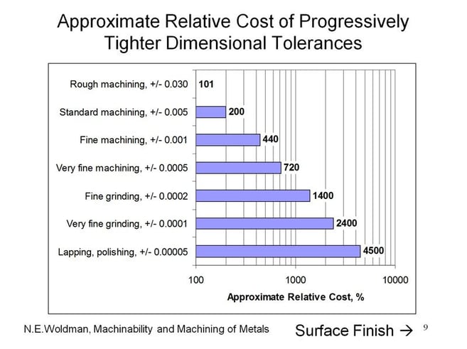
Starting with rough machining (a tolerance of 0.030″), we can see it costs roughly twice as much to make the part with an accuracy of 0.005″ and four times as much to take it to 0.001″. That mythical 0.0001″ tolerance, and I say mythical because it is often overused as a bragging point, will cost 24 times as much to do!
Postscript:
As a someone pointed out, the data above came from a book published in 1951. Has CNC radically changed these figures? A little, but not incredibly. Here are some University of Ohio figures that reflect the CNC age.
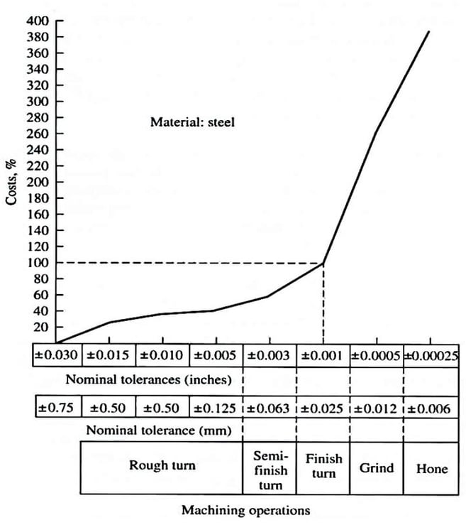
The thing to note is that while the absolute differences in costs have changed somewhat, the shape of the curve is still logarithmic. Costs still go up exponentially as tolerances are made tighter, they just ramp up more gently. Going from 0.001″ to 0.00025″ costs about four times, which is pretty similar to the older figures. If CNC is helping, it is largely at tolerances greater than 0.001″.
Tools to Relieve Tight Tolerances: DFM and GD&T
Before committing a part to manufacturing, be sure to do a careful inventory of the tolerances and make each one is as relaxed as it can possibly be. We’ve written a guide that offers tips on how to reduce the cost of manufacturing at the design stage, a field known as “Design For Manufacturing” or DFM.
Consider also how you’re specifying tolerances. The old-fashioned way is to slap +/- tolerances on every dimension (or perhaps specify a default for dimensions that have no tolerancing). But, Tolerances are nuanced. The more modern approach is called Geometric Dimensioning and Tolerancing or GD&T for short.
Consider just the lowly tolerancing task of specifying the position of a bore center. This can be pretty important for some applications and hence can attract some tight tolerances. The bore is round, but if you think about simple +/- tolerances along say X and Y dimensions, they specify a square region. So, we’re putting a round peg in a square hole?
We can visualize it like this:
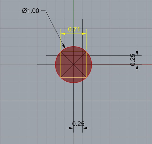
Imagine the red is the allowable area for the bore center, so we try to capture it with +/- dimensions and get the yellow square. The rub is that it really is okay if the bore center falls outside the yellow square as long as it doesn’t fall out side the red area. In fact, we’re having to use overly tight tolerances because the shape of our tolerance zone doesn’t match our needs. That drives up the cost of the part needlessly.
GD&T recognizes this problem and introduces a type of tolerance called True Position. You guessed it–True Position allows a circular tolerance zone and is ideal for our problem. It actually allows looser tolerances and can therefore lead to a part being cheaper to manufacture.