
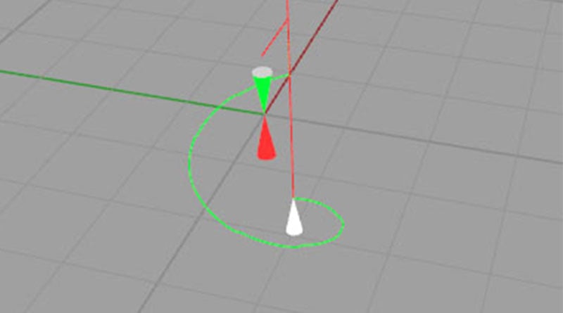
One of the great advantages of CNC over manual machining is the ability to create holes of almost arbitrary size using an end mill that follows a helical path.
Why don’t we make all holes via helical interpolation?
Typically, twist drills are faster, and unless care is exercised they can also be more accurate.
Interpolated holes are a great test of a CNC milling machine because so many things have to work right for one to come out round and on dimension.
The first reaction when an interpolated hole is not round is often that it is a machine problem. Backlash on one or more axes, improper number of steps per inch, and a host of other problems can be the cause. But there are other possibilities too.
For example, suppose you’re machining a ring-shaped part clamped in a vise. You interpolate the center hole and it isn’t right. Maybe the vise is distorting your ring too much by applying pressure to top and bottom but not the sides.
Another is the CAM program. From that same link comes a fellow who says he changed his CAM post to output circles as 4 quadrants instead of a complete circle (e.g. make four moves, each corresponding to a quadrant) which radically improved his accuracy to 0.0002″. I’ve seen this four-quadrant move in posts from other CAM programs, so there must be something to it. Can anyone tell me why?
Probably the most common reason interpolation isn’t accurate is that the requirements to keep the hold round and to proper diameter exceed the ability of the CNC machine to accelerate properly. This one is totally fixable with a little care.
The trick is to take the time to figure out what safe acceleration is for your machine. Get some scrap, and run some tests interpolating holes. Slow down your feeds and speeds until you see where the hole becomes accurate to the tolerance you need.
You can use G-Wizard Calculator’s Helix Mini-Calc to find the feeds and speeds and it will tell you the required acceleration for those feeds and speeds. Dial in the feeds and speeds that worked and use the Mini-Calc to tell you what acceleration that was.
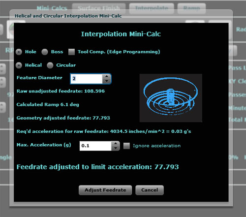
Once you know the safe acceleration your machine can do and hold tolerance, you will be able to adjust the feeds and speeds for any hole size.
Here’s another trick that helps: Do the interpolation both clockwise and counter-clockwise. G-Wizard Editor’s Conversational Programming Wizards will automatically generate the G-code to do that for you.
The alternative for larger holes is usually a boring head. That’s a lot of setup pain and is much slower than interpolation. It’s worth spending time finding the tolerance limits your machine can handle via these techniques.
This post originally appeared on the CNC Cookbook blog.