Have you ever tried a button cutter for milling? If so, you’ll know that these versatile tools can really do a good job for you. They’re commonly used for pocketing, die/mold roughing, face milling, slotting, step milling, and even helical interpolation of holes. There’s a lot to recommend round inserts as they have a number of properties that contribute to their success. If you’ve used one turning, you know that their large radius can yield some very nice surface finishes. They can leave a good finish when milling too, but they have a number of other advantages. Their round shape makes them particularly strong as they have no weak corners that can chip. If you do wear or chip one, they can be rotated to expose a fresh edge. They’re advantageous for lighter machines too. When operating at heavier depths of cut, they create cutting forces that are more radial. But, by taking a lighter depth of cut, they transition to behave more like high-feed machining tools. This means most of the cutting forces are directed straight up the spindle, which is the strongest rigidity on any machine. That’s one reason plunge milling is so advantageous on light machines. Button cutters provide an alternative. It seems that for whatever reason, the physics of cutting favors circles. HSM toolpaths do better than conventional paths by adopting loops rather than sharp corners. And button cutters do well because corners on inserts are a weak point that can chip or break off. You can load up a button cutter pretty hard and they’ll hang in there. If you do manage to chip one, just rotate the insert until the chipped portion is not being used and keep going.

In the most demanding applications, button cutters compete with high-feed cutters. For many shops, a high-feed cutter is a direct replacement of their button cutter that allows them to crank up the feeds and speeds. For this reason, some have said button cutters are on their way out. But, there are cases where the button cutter still makes better economic sense:
- On older or lighter machines that can achieve the performance needed by high-feed cutters.
- With extremely tough materials where the ability to rotate a worn insert and keep going gives button cutters an edge.
- In re-roughing applications and applications with extremely hard materials where a button cutter’s round inserts are just stronger and tougher, so they last longer. Machining of welded parts is particularly well suited since the button cutter handles the hardened welds so well.
The physics of button cutters mean that some very special calculations have to be done when figuring their feeds and speeds. There are several important issues to consider:
- Cuts should be made with a depth of cut less than the radius of the insert. That means the diameter of the tool is a function of the depth of cut because of the radius that is the edge of the cutter, just like a ball nose end mill.
- Toroidal cutters are subject to chip thinning in two dimensions. Like any rotary cutter, if the width of the cut is less than half the diameter, chip thinning occurs. There’s a diagram showing how this geometry works as part of our speeds and feeds tutorial. It’s very important to consider chip thinning or your actual chipload may be lower than you expect and the tool can start rubbing, which will dramatically reduce cutter life. However, when you not only have a rotating tool but one with round inserts, you get chip thinning in both the radial and axial planes.
- Because of their unique design, toroidal cutters can tolerate quite a bit more chipload than most other kinds of indexable cutter. There’s no corner weak point that can be easily damaged by cuts that are too aggressive. This is also true to a certain extent for bull nose end mills, which are just end mills whose bottom edge has been given a radius. Think of them as button cutters whose round inserts have a really tiny radius.
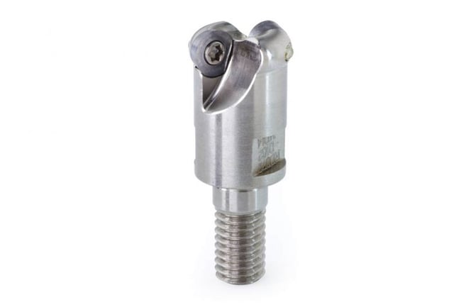
- While the cutter pictured doesn’t do so, more exotic designs may also “lay down” the round insert slightly, introducing a lead angle on top of everything else that is going on with the geometry.
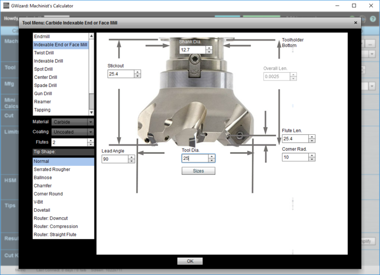
Suffice it to say that simple tables are not going to yield the best results. You need to be prepared to do some extra calculating, or to use a calculator like my G-Wizard Software that does all that for you. There is a lot else to recommend button cutters. For example, they make great tools for helical interpolation of holes. And, they tend to convert a lot more of the cutting force to the axial direction, which is the stiffest direction for most machines. The lower the depth of cut, the more of the force is translated axially. Lastly, when roughing out steps, you get a smooth scallop instead of a shoulder with a corner. This can make life easier for your finishing cutter. Before we leave the topic, let’s consider a few basics in terms of how to operate a button cutter: 1. Try to keep at least a 75% stepover so the inserts spend a lot of their time in the cut. This minimizes the chip thinning in one direction, but it’s okay since round inserts get chip thinning in the other direction. The reason to maximize the stepover is that most of the wear and tear on the inserts is on entry into the cut. 2. Speaking of entry into the cut, arcing in and helixing in are far preferably to plunging in. Try my Conversational CNC Surfacing Wizard and Hole Wizard for some gentle tool paths when using one of the cutters for face milling or helical interpolating holes. 3. Keep the depth of cut below the cutter radius. 4. As you’re considering the best depth of cut, try to keep the width of cut relatively high (about 75% as mentioned in #1). Keep depth of cut less than the insert radius. In fact less is more with these cutters, so drop it down as far as you can while keeping acceptible Material Removal Rates. You can play with these tradeoffs using G-Wizard Calculator to find the sweet spot. Setting Up G-Wizard Calculator for a Button Cutter Setting up a Button Cutter in G-Wizard is pretty simple. We’ll use Tormach’s 25mm cutter as the example. As mentioned, it has a 25mm diameter. It uses a round insert with a 10mm radius. So, choose an Indexable end or face mill tool type, tell it how many inserts (3 for the Tormach) or flutes, and click the “Geometry” button. Set it up as shown: 
Basically, you just want to set it up with the right diameter and corner radius. By the way, there’s a trick if you are running in Imperial and want to enter metric values. So, for the cut diameter, I entered “25/25.4” and hit "Enter" and it did the calculation right in the field. You can also enter “25m” to convert mm to inches and 25i to convert inches to millimeters. This post originally appeared on the CNC Cookbook blog.


