
This post originally appeared on the In the Loupe blog.
Thread milling can present a machinist with many challenges. While thread mills are capable of producing threads with relative ease, there are a lot of considerations that machinists must make prior to beginning the job in order to gain consistent results. To conceptualize these features and choose the right tool, machinists must first understand basic thread milling applications.
What is a thread?
The primary function of a thread is to form a coupling between two different mechanisms. Think of the cap on your water bottle. The cap couples with the top of the bottle in order to create a water tight seal. This coupling can transmit motion and help to obtain mechanical advantages. Below are some important terms to know in order to understand threads.
Root – That surface of the thread which joins the flanks of adjacent thread forms and is immediately adjacent to the cylinder or cone from which the thread projects.
Flank – The flank of a thread is either surface connecting the crest with the root. The flank surface intersection with an axial plane is theoretically a straight line.
Crest - This is that surface of a thread which joins the flanks of the thread and is farthest from the cylinder or cone from which the thread projects.
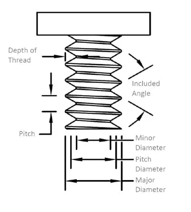
Pitch – The pitch of a thread having uniform spacing is the distance measured parallelwith its axis between corresponding points on adjacent thread forms in the same axial plane and on the same side of the axis. Pitch is equal to the lead divided by the number of thread starts.
Major Diameter – On a straight thread the major diameter is that of the major cylinder.On a taper thread the major diameter at a given position on the thread axis is that of the major cone at that position.
Minor Diameter – On a straight thread the minor diameter is that of the minor cylinder. On a taper thread the minor diameter at a given position on the thread axis is that of the minor cone at that position.
Helix Angle – On a straight thread, the helix angle is the angle made by the helix of the thread and its relation to the thread axis. On a taper thread, the helix angle at a given axial position is the angle made by the conical spiral of the thread with the axis of the thread. The helix angle is the complement of the lead angle.
Depth of Thread Engagement – The depth (or height) of thread engagement between two coaxially assembled mating threads is the radial distance by which their thread forms overlap each other.
External Thread – A thread on a cylindrical or conical external surface.
Internal Thread – A thread on a cylindrical or conical internal surface.
Class of Thread – The class of a thread is an alphanumerical designation to indicate the standard grade of tolerance and allowance specified for a thread.
Source: Machinery’s Handbook 29th Edition
Types of Threads & Their Common Applications:
ISO Metric, American UN: This thread type is used for general purposes, including for screws. Features a 60° thread form.
British Standard, Whitworth: This thread form includes a 55° thread form and is often used when a water tight seal is needed.
NPT: Meaning National Pipe Tapered, this thread, like the Whitworth Thread Form, is also internal. See the above video for an example of an NPT thread.
UNJ, MJ: This type of thread is often used in the Aerospace industry and features a radius at the root of the thread.
ACME, Trapezoidal: ACME threads are screw thread profiles that feature a trapezoidal outline, and are most commonly used for power screws.
Buttress Threads: Designed for applications that involve particularly high stresses along the thread axis in one direction. The thread angle on these threads is 45° with a perpendicular flat on the front or “load resisting face.”
Thread Designations
Threads must hold certain tolerances, known as thread designations, in order to join together properly. International standards have been developed for threads. Below are examples of Metric, UN, and Acme Thread Designations. It is important to note that not all designations will be uniform, as some tolerances will include diameter tolerances while others will include class of fit.
Metric Thread Designations
M12 x 1.75 – 4h - LH
In this scenario, “M” designates a Metric Thread Designation, 12 refers to the Nominal Diameter, 1.75 is the pitch, 4h is the “Class of Fit,” and “LH” means “Left-Hand.”
UN Thread Designations
¾ 10 UNC 2A LH
For this UN Thread Designation, ¾ refers to the thread’s major diameter, where 10 references the number of threads per inch. UNC stands for the thread series; and 2A means the class of thread. The “A” is used to designate external threads, while “B” is for internal threads. For these style threads, there are 6 other classes of fit; 1B, 2B, and 3B for internal threads; and 1A, 2A, and 3A for external threads.
ACME Thread Designations
A 1 025 20-X
For this ACME Thread Designation, A refers to “Acme,” while 1 is the number of thread starts. The basic major diameter is called out by 025 (Meaning 1/4”) while 20 is the callout for number of threads per inch. X is a placeholder for a number designating the purpose of the thread. A number 1 means it’s for a screw, while 2 means it’s for a nut, and 3 refers to a flange.
How are threads measured?
Threads are measured using go and no-go gauges. These gauges are inspection tools used to ensure the that the thread is the right size and has the correct pitch. The go gauge ensures the pitch diameter falls below the maximum requirement, while the no-go gauge verifies that the pitch diameter is above the minimum requirement. These gauges must be used carefully to ensure that the threads are not damaged.
Thread Milling Considerations
Thread milling is the interpolation of a thread mill around or inside a workpiece to create a desired thread form on a workpiece. Multiple radial passes during milling offer good chip control. Remember, though, that thread milling needs to be performed on machines capable of moving on the X, Y, and Z axis simultaneously.
5 Tips for Successful Thread Milling Operations:
1. Opt for a Quality Tooling Manufacturer
There is no substitute for adequate tooling. To avoid tool failure and machining mishaps, opt for a quality manufacturer for High Performance Drills for your starter holes, as well as for your thread milling solutions. Harvey Tool fully stocks several types of threadmills, including Single Form, Tri-Form, and Multi-Form Thread Milling Cutters. In addition, the 60° Double Angle Shank Cutter can be used for thread milling.

Image Courtesy of @Avantmfg
2. Select a Proper Cutter Diameter
Choose only a cutter diameter as large as you need. A smaller cutter diameter will help achieve higher quality threads.
3. Ensure You’re Comfortable with Your Tool Path
Your chosen tool path will determine left hand or right hand threads.
Right-hand internal thread milling is where cutters move counterclockwise in an upwards direction to ensure that climb milling is achieved.
Left-hand internal thread milling a left-hand thread follows in the opposite direction, from top to bottom, also in a counterclockwise path to ensure that climb milling is achieved.
4. Assess Number of Radial Passes Needed
In difficult applications, using more passes may be necessary to achieve desired quality. Separating the thread milling operation into several radial passes achieves a finer quality of thread and improves security against tool breakage in difficult materials. In addition, thread milling with several radial passes also improves thread tolerance due to reduced tool deflection. This gives greater security in long overhangs and unstable conditions.
5. Review Chip Evacuation Strategy
Are you taking the necessary steps to avoid chip recutting due to inefficient chip evacuation? If not, your thread may fall out of tolerance. Opt for a strategy that includes coolant, lubricant, and tool retractions.
In Summary
Just looking at a threading tool can be confusing - it is sometimes hard to conceptualize how these tools are able to get the job done. But with proper understanding of call, methods, and best practices, machinists can feel confident when beginning their operation.